How to Order Pipe Flanges – Part 3

Step 3 – Define the Flange Facing


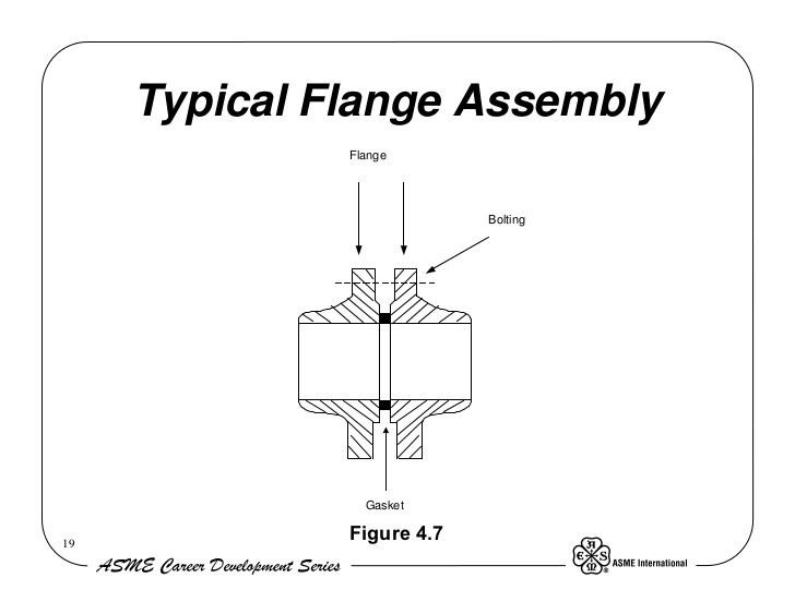
The face of the flange is the sealing surface.  In nearly all cases a gasket is used between flange facings (the most notable exception is resilient seated lug and wafer butterfly valves.)  Any type of pipe flange can be ordered with any of the facings mentioned here.

This chart shows the most common flange faces.
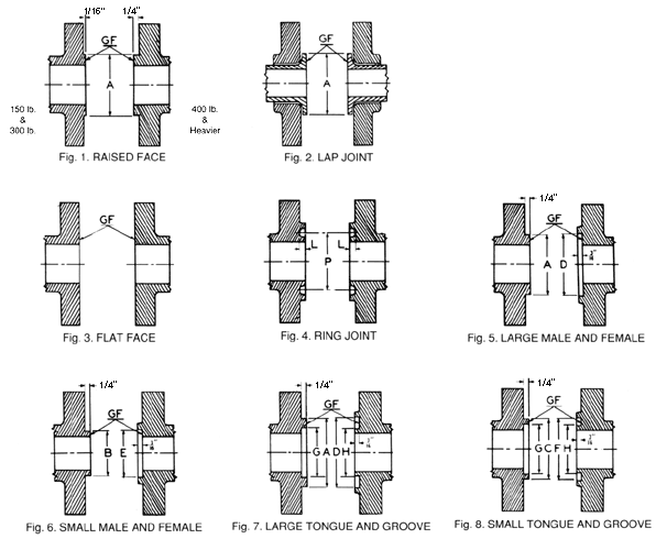


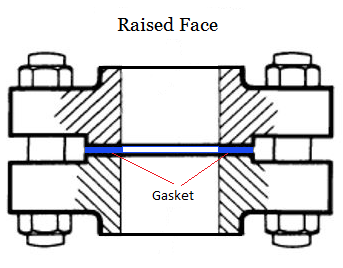
Raised Face (RF) is the most common industrial flange facing.  Class 150 and 300 have a 1/16” raised face and class 400 thru 2500 have a ¼” raised face. This raised section is the sealing surface of the flange.  RF flanges are designed to use a Ring gasket; however a Full Face gasket will also work.  By creating a gap at the bolt circle, the RF flange exerts more pressure on the sealing surface than a flat face flange.
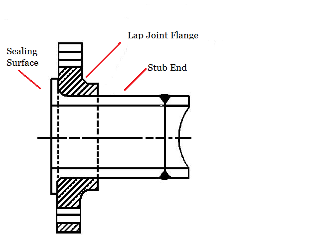


Lap joint flanges have flat faces.  The face of a lap joint is not used for sealing.  The lap joint is used in conjunction with a stub end and the sealing surface is on the stub end.  The sealing surface on the stub end is similar to a RF flange.


Flat Face (FF) flanges utilize the entire face for sealing.  They are used for lower pressure (up to 250 psi) applications.  FF flanges are designed to use a Full Face gasket; however a Ring gasket will also work.  It is possible to mount a FF to a RF flange and have them seal, however it is not advisable.
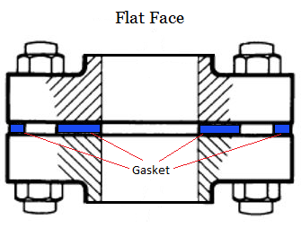
 

Flange facings can be modified from their original manufacture as long as the standard's minimum dimensions are maintained.  For example a RF flange can be machined to a FF or RTJ flange.

Standard facings can have a serrated concentric or serrated spiral finish.


Part 4 coming soon...


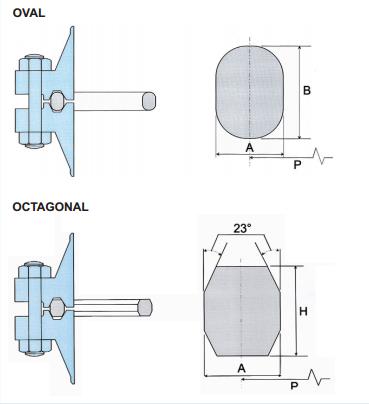
Ring Joint or Ring Type Joint (RTJ) facings use a metal ring gasket.  The gasket is usually oval or octagonal in shape and it fits into a groove on the flange.  RTJ flanges have a raised race and are used for high pressure and high temperature applications.


Male & Female and Tongue & Groove facings are not very common and are used in only a few niche applications.  These flanges use a Ring gasket that fits into the female or groove face.
How to Order Pipe Flanges – Part 2

How to order Pipe Flanges – Part 1 (con't)

Dimensional standards are the same for all materials.  In other words, the dimensions of a 6” ASME B16.5 Class 150 flange will be the same for carbon steel, stainless steel, Alloy 20 or aluminum.  More information on materials can be found in Part 4.

Final note on standards.  Standards are continually revised, broadened and evolving. And so are the standards organizations.  For instance the flange standard B16.5 was first published by ASA.  That changed to ANSI and then to ANSI/ASME and now it is just ASME.  It is very common for specifications to include reference to older publications and presumed that the most current standard be utilized.  


Step 2 – Define the Pressure Class

Pressure class further defines flange dimensions.  The pressure class is not the pressure limit of the flange; it is more like a starting point.

This chart shows the pressure classes defined by each of the standards listed.

ANSI B16.1ASME B16.24ASME B16.47 Series AASME B16.47 Series BASME B16.5AWWA C207AWWA C115API 6AAPI 17DISO 7005
Class 125Class 150Class 150Class 75Class 150Class BClass 1252000 PSI5000 PSIPN2.5
Class 250Class 300Class 300Class 150Class 300Class D3000 PSI10000 PSIPN6
Class 400Class 400Class 300Class 400Class E5000 PSI15000 PSIPN10
Class 600Class 600Class 400Class 600Class F10000 PSIPN16
Class 900Class 900Class 600Class 90015000 PSIPN25
Class 1500Class 900Class 150020000 PSIPN40
Class 2500Class 2500

There are 4 factors that determine the actual working pressure and pressure limits of flanges within each pressure class.

  1. The dimensions; the diameter, thickness, number and size of bolts.
  2. The material; even though the pressure class and dimensions are the same for all materials in each standard, the actual pressure and temperature limits are different for every material.
  3. The temperature; as internal and/or external temperatures increase pressure limits decrease.
  4. The size; within some pressure classes, the limits will be less for larger pipe sizes.


The following charts are examples of flange pressure/temperature ratings.  These charts have been compiled from reliable sources; however they are NOT a substitute for professional engineering and they are not applicable to all applications.  Please use these charts as a reference only.  For critical applications please consult a qualified engineer.


ANSI B16.1 A126B Cast Iron Maximum Working Pressure (psig)

Pressure Class125125125250250
Temperature (F)1"-12" Pipe Size14"-24" Pipe Size30"-48" Pipe Size1"-12" Pipe Size14"-24" Pipe Size
-20 up to 150200150150500300
200190135115460280
225180130100440270
25017512585415260
27517012065395250
30016511050375240
325155105-355230
350150100-335220
375145--315210
400140--290200
425130--270-
450125--250-


ASME B16.5 A105 Forged Carbon Steel Maximum Working Pressure (psig)

Pressure Class15030040060090015002500
Temperature (F)1/2"-24" Pipe Size1/2"-24" Pipe Size1/2"-24" Pipe Size1/2"-24" Pipe Size3"-24" Pipe Size1/2"-24" Pipe Size1/2"-12" Pipe Size
-20 to 10029075010001500225037506250
20026075010001500225037506250
3002307309701455218536406070
4002007059401405211035205865
5001706658851330199533255540
6001406058051210181530255040
6501255907851175176529404905
7001105557401110166527754630
750955056751015152025354230
80080410550825123520553430


ASME B16.5 A182 F316L Stainless Steel Maximum Working Pressure (psig)

Pressure Class15030040060090015002500
Temperature (F)1/2"-24" Pipe Size1/2"-24" Pipe Size1/2"-24" Pipe Size1/2"-24" Pipe Size3"-24" Pipe Size1/2"-24" Pipe Size1/2"-12" Pipe Size
-20 to 1002306008001200180030005000
2001955056751015152025304220
300175455605910136022703780
400160415550825124020653440
500145380510765114819103180
600140360480720108018003000
650125350470700105017502920
700110345460685103017152860
75095335450670101016802800
8008033044066098516452740


Because the pressure class determines the bolting dimensions and the pressure limits, this must be defined when ordering pipe flanges.  If you have any questions, please contact one of our friendly sales people.  We are eager to help!


Step 3 - Define the Flange Facing


How to Order Pipe Flanges – Part 1

Pipe flanges are used for connecting pipe, valves, fittings, strainers, pumps and equipment.  Nearly all pipe flanges are round discs; however they can also be square, rectangular or oval.  Flanges that are not round are designed for very specific applications such as hydraulics, ammonia service, hand rails and meters.  In this tutorial we will examine only pressure rated round flanges that connect to pipe.

Step 1 - Define the Standard or Specification.   

Over 100 years ago some very smart engineers figured out that different manufacturers build different components of a piping system.  And in order for these components to easily bolt together, standard dimensions would be required.  So they made a lot of calculations factoring in flow characteristics and pressure ratings and then designed a few flanges.  They sent these dimensions and calculations to their peers, the piping component manufacturers and probably a few insurance companies.  Eventually they all nodded yes and a standard was born.

Over the years more standards were added, more sizes and pressure classes were added and more definitions were added.  Mostly the standards detail the flange dimensions and tolerances, but there are also standards that detail the chemistry of the materials. 

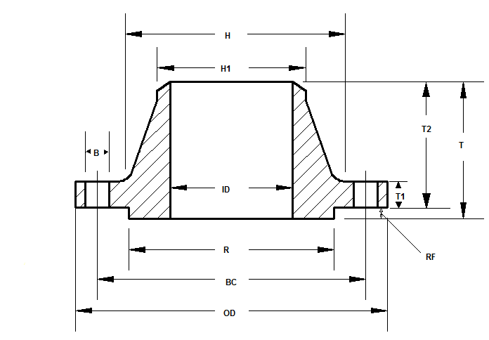
Details of the flange dimensions include the number of bolt holes, the size of the bolt holes, the diameter of the bolt circle and the shape of the flange face (the sealing surface.) 

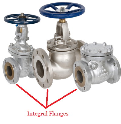
Pumps, valves, strainers, pipe fittings and piping equipment are often produced and sold with integral flanges.  In order to connect these to a piping system, a mating flange is required.  This mating flange must have the same bolting dimensions and matching facing for the flange to connect and seal. 

The following criterion is required when ordering flanges, but only if you want them to connect and seal, which we assume you do.

  • Standard or Specification
  • Pressure Class
  • Facing
  • Material
  • Pipe Size
  • Connection Type
  • Description

This list may look difficult at first, but we’ll walk you through it so it’s a little easier.


All of these dimensions are critical for bolting and sealing.


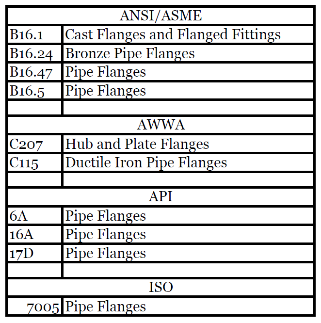
Each of these standards list flanges by pipe size, pressure class, facing and pipe connection.  Pipe size and pressure class determine the bolting pattern.  Facing determines the sealing surface.  Some bolt patterns and facing are shared across these standards and are primarily based on the ANSI/ASME B16.5 standard.  Because not all the dimensions are shared, we recommend you start by defining the applicable standard. 

If you are mixing standards or adapting, we suggest you consult a professional, like one of our friendly sales people.  If you are unsure which standard to adopt, we again suggest you consult a professional… like one of our friendly sales people.


How to Order Pipe Flanges - Part 2

This chart shows the most common dimensional standards used for industrial and commercial metal flanges.

How to Identify a Pipe Flange

You're changing a connection on an existing system and you need to identify a flange. It may be ANSI Class 150, it may be AWWA Class D or it may be a DIN standard. Nearly all flanges are now stamped with identifying numbers on the side but you cannot find any markings on your flange, so what do you do?

There are at least a dozen standards for pipe flanges. Nearly all are unique with very little interchangeability. The standard could be based on an ASME, ASTM, ANSI, API, MSS, AWWA, DIN, standard recognized industry guidelines or it may be based on specific application guidelines.

Fortunately there is a way to identify your flange. With the following information a qualified supplier should be able to identify the correct standard.

These first three are critical and may be enough to identify your flange.

Diameter of Bolt Circle (Centerline to centerline across the flange. This may require un-bolting the flange)
Number of Bolt Holes
Diameter of Bolt Hole or Bolt

Additional information you will need is listed below.

Type of Material
Flange Facing or type of Gasket used
Outside Diameter of Flange
Thickness of Flange
Pipe Connection
Pipe Size